DInSAR service specifications
![]()
This InSAR service derives line of sight displacement, interferometric phase and coherence from a pair of SAR complex images. It supports Sentinel-1 SLC data in TOPSAR (IW and EW) mode and SAOCOM SLC data in Stripmap (SM) mode only
 The tutorial of the DInSAR service is available in this section.
Service Description
The DInSAR Displacement Mapping (DInSAR) service performs an interferometric computation between a pair of SAR complex datasets to obtain Line of Sight (LOS) displacement, interferometric phase and coherence. The service is developed by Terradue and AUTh/EO.Lab.
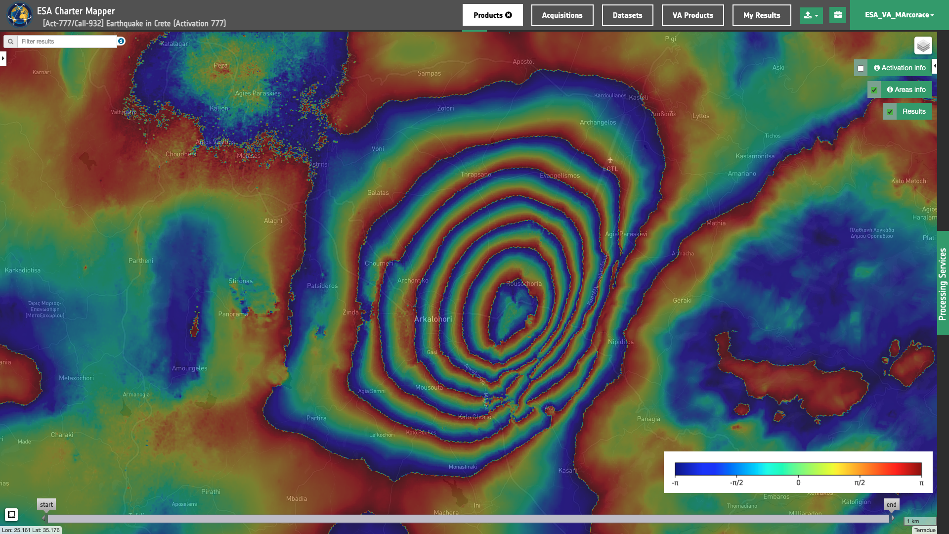
Figure 1 - Interferometric phase map highlighting the co-seismic ground deformation induced by the Crete M6.0 Earthquake, September 2021. The interferometric phase derived from the DInSAR service using Copernicus Sentinel-1 mission data. Reference 24th and secondary 30th Sep 2021.
Warning
The DInSAR service currently supports Sentinel-1 SLC datasets in TOPSAR (IW and EW) mode, and SAOCOM-1 SLC datasets in Stripmap (SM) mode only.
Note
The DInSAR processor is offered in the ESA Charter Mapper as 2 separated on-demand services:
- the
DInSAR Displacement Mapping - Sentinel-1 (DInSAR-S1),
![]()
- and
DInSAR Displacement Mapping - Stripmap (DInSAR-SM).
![]()
The coherence between the reference and the secondary indicates the quality of the interferometric phase. High coherence values highlight a strong similarity in the interferometric pair and creates the better condition for processing (e.g. Displacement mapping in LOS). Instead, low coherence values result into poor interferometric results (e.g. over vegetation in due to volumetric scattering).
The DInSAR service relies on the ESA SNAP1,2 software which is a common architecture for all Sentinel Toolboxes and is ideal for Earth Observation processing and analysis. The flowchart in the next section describes the entire DInSAR workflow. For the two-dimensional phase unwrapping DInSAR employs the SNAPHU3 software from the Stanford Radar Interferometry Research Group. In the creation of the interferogram the Goldstein4 phase filtering is applied to enhance the signal-to-noise ratio of the interferometric phase image and better identify fringes. To Subtract topographic phase and in the Geocoding and Back Geocoding steps DInSAR uses the Copernicus DEM, COP-DEM5, at 30m resolution as Digital Elevation Model. In the geocoding DInSAR employs an automatic UTM zone reprojection of results.
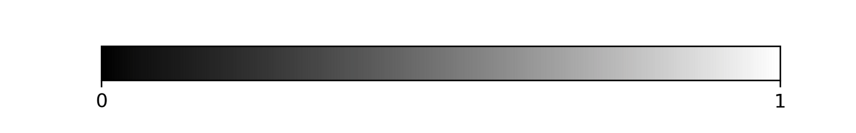
Once Line of Sight (LOS) displacement, interferometric phase and coherence single-band assets are generated, the service also derives three overview products after a normalization of each single-band asset in its valid range (e.g. [-3.14,3.14] for the interferometric phase) and a rescaling to 8-bit range. The color maps6 adopted in the creation of the RGBA are the followings:
- Sequential Black to White color map
Grayfor the interferometric coherence (higher coherence values in white tones),
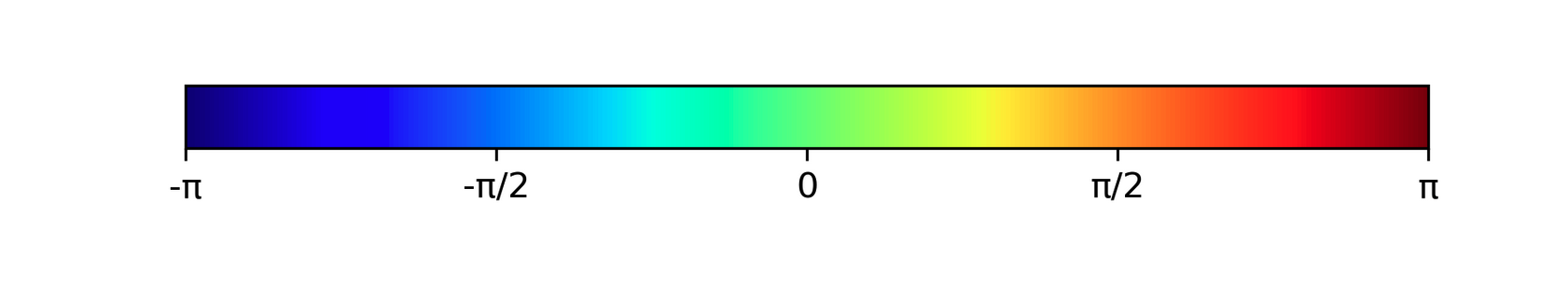
- Multicolor
Jetcolor map for the interferometric phase,
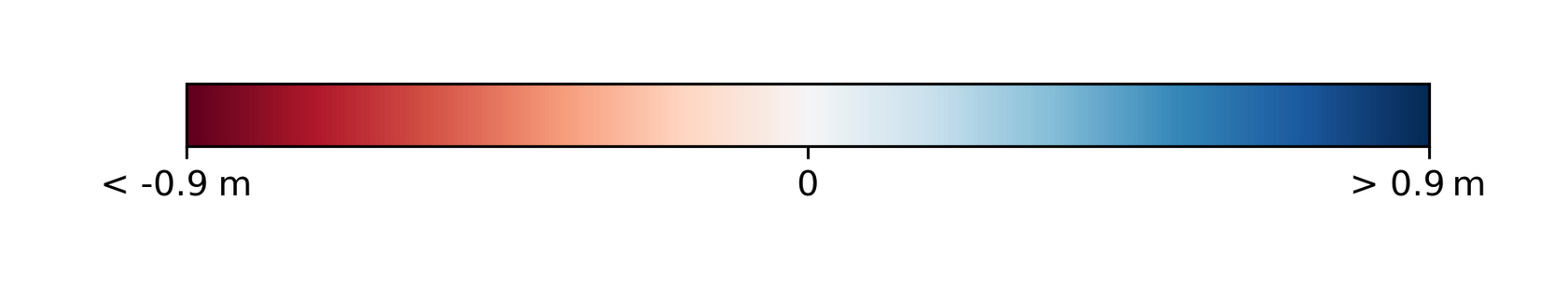
- Diverging Red to Blue
RdBucolor map for the LOS displacement (negative LOS displacement values in red shadows and positive in blue shadows).
Note
The here given legend for LOS Displacement is just an example since min and max are derived by the asset.
Info
A negative LOS displacement value (red color) indicates a movement of the surface farer away from the sensor along the LOS. Viceversa, positive displacement (blue color) for a surface moving closer to the sensor along the LOS. Negative or positive values indicates a surface movement consistent with the satellite orbit direction.
Warning
Signed LOS displacement values are always relative to the reference image. A convention is to set the reference as the oldest SAR acquisition in the pair. Thus, the most recent acquired image of the pair can be used as secondary to check how the motion was evolved.
Workflow
Below is described the workflow for each version of the DInSAR on-demand processing service, the DInSAR Displacement Mapping - Sentinel-1 (DInSAR-S1) and DInSAR Displacement Mapping - Stripmap (DInSAR-SM).
DInSAR-S1 workflow
The DInSAR-S1 service implements the workflow depicted below.
DInSAR-SM workflow
The DInSAR-SM service implements the workflow depicted below.
Input
The DInSAR service requires in input a pair of SLC Datasets (interferometric pair) from supported SAR sensors. Input SAR complex imagery must be a pair from the same mission, track, and polarization.
Warning
This service currently supports Sentinel-1 SLC data in TOPSAR (IW and EW) mode, and SAR complex imagery in Stripmap (SM) mode from the SAOCOM mission only.
Parameters
The DInSAR service requires a specified number of mandatory and optional parameters. Table 1 describes the service parameters.
| Parameter | Description | Required | Default value |
|---|---|---|---|
| Reference SLC dataset | Input reference SLC Dataset with intensity and phase recorded as complex numbers | YES | |
| Secondary SLC dataset | Input secondary SLC Dataset with intensity and phase recorded as complex numbers | YES | |
| Processing type | Flag to choose DEM or XCORR as processing type. | YES* | DEM |
| Area of Interest | Area of interest expressed in WKT | NO |
Table 1 - Service parameters for the DInSAR processor.
Note
This parameter is available only for DInSAR-SM. The DInSAR-S1 service does not include this parameter.
More information about the service parameters are given below.
Reference and secondary SAR SLC datasets
The reference and secondary SAR SLC datasets must come from the same sensor and shall have the same radar geometry (incident angle, orbit path). Input reference and secondary SAR SLC datasets shall have an intersection of 40% of their total footprint area.
Warning
In the choice of reference and secondary be aware that LOS Displacement values are always relative to the master image.
Processing type (for Stripmap only)
With this parameter the user shall choose among the 2 possible processing types for the generation of the interferogram:
-
DEM - a DEM assisted co-registration is employed for the interferogram generation,
-
XCORR - the interferogram is generated without the DEM through a sequence of stacking, cross-correlation, and warping of reference and secondary.
AOI (optional)
This last parameter (optional) may define the area of interest expressed as a Well-Known Text value.
Warning
The AOI specified by the user shall be fully included in the intersection of reference and secondary
Tip
In the definition of “Area of interest as Well Known Text” it is possible to apply as AOI the drawn polygon defined with the area filter. To do so, click on the button in the left side of the "Area of interest expressed as Well-known text" box and select the option AOI from the list. The platform will automatically fill the parameter value with the rectangular bounding box taken from the current search area in WKT format.
Output
Output products of the DInSAR service are the following single-band and overview assets:
- Product A: Interferometric Coherence
- Product B: Interferometric Phase
- Product C: LOS Displacement
- Product D: Interferometric Coherence overview
- Product E: Interferometric Phase overview
- Product F: LOS Displacement overview
Output geocoded assets are given in COG format and in the UTM projected coordinate system (WGS84 datum).
The below tables provide Product Specifications for the DInSAR service.
| Attribute | Value / description |
|---|---|
| Long Name | Interferometric Coherence product |
| Short Name | coh_b_pp_YYYYMMDD_YYYYMMDD (where b the SAR-band [x,c,l], pp is the polarization [hh, hv, vh, vv], YYYYMMDD is the date of Reference and Secondary Dataset |
| Description | Interferometric coherence computed on input SLC couple, it indicates where the phase information is coherent (single band ssset) |
| Data Type | Float 32 bit |
| Band | 1 |
| Format | COG |
| Projection | UTM (WGS84) |
| Valid Range | [0 - 1] |
| Attribute | Value / description |
|---|---|
| Long Name | Interferometric Phase product |
| Short Name | phase_b_pp_YYYYMMDD_YYYYMMDD (where b the SAR-band [x,c,l], pp is the polarization [hh, hv, vh, vv], YYYYMMDD is the date of Reference and Secondary Datasets |
| Description | Interferometric phase computed from input SLC couple (Single band asset). |
| Data Type | Float 32 bit |
| Band | 1 |
| Format | COG |
| Projection | UTM (WGS84) |
| Fill Value | 0 |
| Attribute | Value / description |
|---|---|
| Long Name | Line of Sight Displacement |
| Short Name | displacement_b_pp_YYYYMMDD_YYYYMMDD (where b the SAR-band [x,c,l], pp is the polarization [hh, hv, vh, vv], YYYYMMDD is the date of Reference and Secondary Datasets |
| Description | Line of Sight Displacement in m |
| Data Type | Float 32 bit |
| Band | 1 |
| Format | COG |
| Projection | UTM (WGS84) |
| Unit | m |
| Attribute | Value / description |
|---|---|
| Long Name | Interferometric Coherence overview |
| Short Name | overview-coherence |
| Description | Visual product derived from the Interferometric Coherence product using the "Gray" color map |
| Data Type | Unsigned 8-bit Integer |
| Band | 4 |
| Format | COG |
| Projection | UTM (WGS84) |
| Valid Range | [1 - 255] |
| Fill Value | 0 |
| Attribute | Value / description |
|---|---|
| Long Name | Interferometric Phase overview |
| Short Name | overview-phase |
| Description | Visual product derived from the Interferometric Phase product in radians using the "Jet" color map |
| Data Type | Unsigned 8-bit Integer |
| Band | 4 |
| Format | COG |
| Projection | UTM (WGS84) |
| Valid Range | [1 - 255] |
| Fill Value | 0 |
| Attribute | Value / description |
|---|---|
| Long Name | Line of Sight Displacement overview |
| Short Name | overview-displacement |
| Description | Visual product derived from the Line of Sight Displacement in m using a "RdBu" color map |
| Data Type | Unsigned 8-bit Integer |
| Band | 4 |
| Format | COG |
| Projection | UTM (WGS84) |
| Valid Range | [1 - 255] |
| Fill Value | 0 |
-
ESA Science Toolbox Exploitation Platform, SNAP Toolbox available at https://step.esa.int. ↩
-
SNAPISTA, SNAP GPT Python wrapper documentation available at https://snap-contrib.github.io/snapista/. ↩
-
Stanford Radar Interferometry Research Group, Statistical-Cost, Network-Flow Algorithm for Phase Unwrapping SNAPHU software, available at https://web.stanford.edu. ↩
-
Goldstein, Richard & Werner, Charles, (1998), "Radar interferogram filtering for geophysical applications", Geophysical Research Letters, 25, 4035-4038. Geophysical Research Letters, 25. DOI: 10.1029/1998GL900033. ↩
-
Copernicus, "Copernicus DEM - Global and European Digital Elevation Model (COP-DEM)", available at: https://spacedata.copernicus.eu. ↩
-
Matplotlib, Color maps, available at https://matplotlib.org. ↩